Welding robot programming: typical errors and settings
Other
Welding robot programming: typical errors and settings | Syneo
Practical guide to welding robots: the most common programming errors (TCP, coordinates, speed profile), sensors, peripherals, and quick setup tips for stable welds.
welding, robot programming, robotics, TCP, seam tracking, sensors, cell integration, quality, maintenance, WPS
February 11, 2026

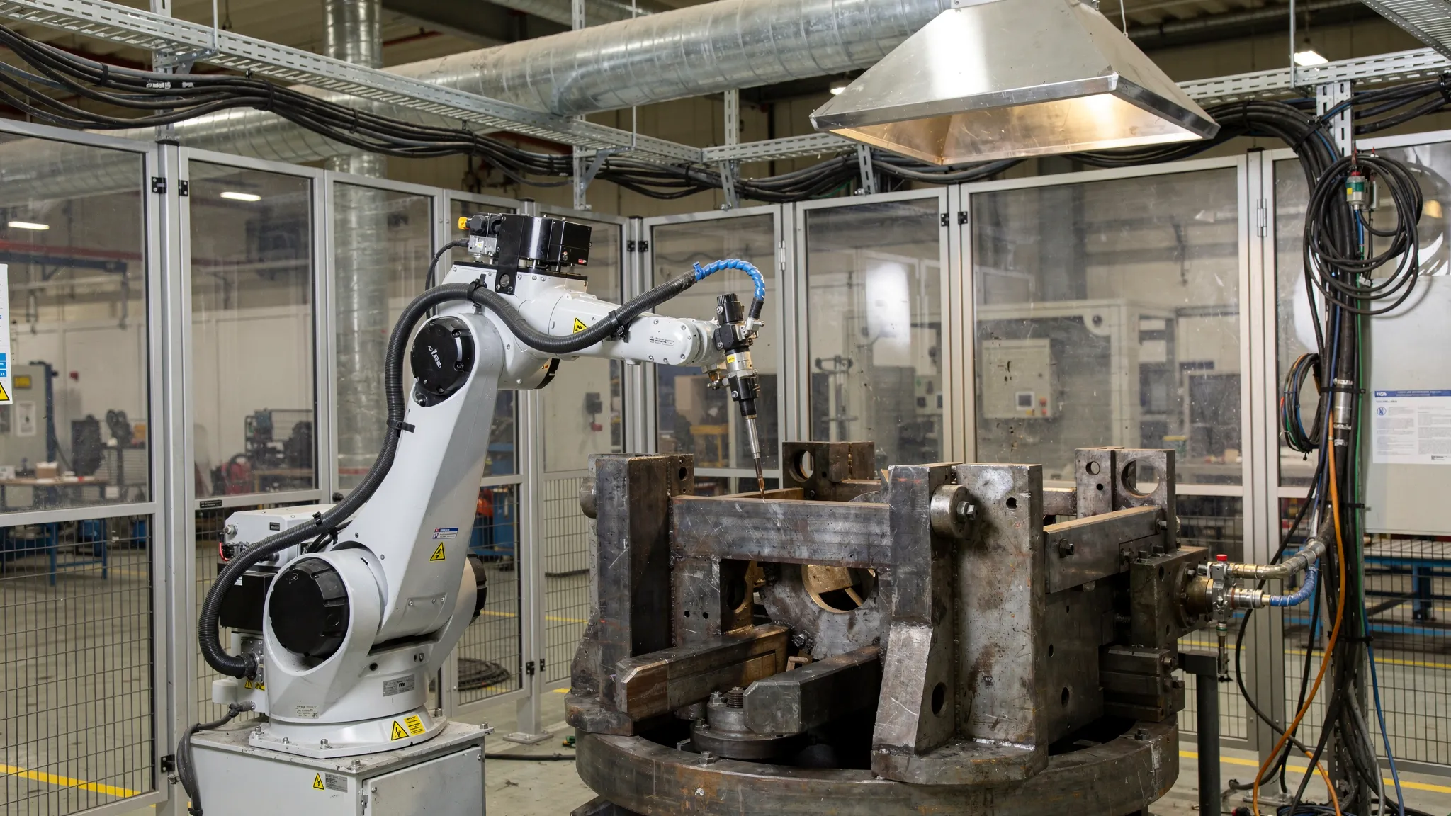
The welding cell produces truly stable results when the welding robot programming not only "moves" the arm, but also coordinates the path, the arc process, the clamping, and the peripherals. Most problems (spatter, undercutting, porosity, collision, fluctuating weld pattern, scrap, excessively long cycle time) are not caused by a single bad parameter, but by the accumulation of several small deviations.
This article reviews the most common errors that occur during production and the settings that can typically be used to quickly improve quality and stability, whether you are using teach pendant or offline (OP) programming.
Troubleshooting mindset: 3 layers that are worth separating
The key to effective diagnosis is to first identify which "layer" the problem arises in:
Geometry and repeatability: workpiece position, clamping, positioning, distortion, wear, backlash.
Robotics and trajectory: TCP and coordinate systems, approximations, orientation, speed profile, arc switch timing.
Welding technology: WPS logic, current, voltage, wire feed, travel speed, gas, CTWD (contact tip-to-work distance), weave, crater filling.
If you mix these three layers, you typically "overcompensate" on the welding machine, while the real cause is, for example, a slipped zero point or an unstable clamping.
Typical programming errors that immediately ruin the seam
1) Bad TCP or inaccurate TCP calibration
Symptoms:
the seam "runs out" from the corner, the gap is unstable
The same program behaves differently in another shift or with another gun.
The angle of the gun does not maintain the set tilt, especially on curves and turns.
What happens in the background? The robot calculates the path relative to the TCP (Tool Center Point). If the TCP is incorrect, all points will be "correct" at the moment of teaching, but the orientation during movement and path tracking will be distorted.
Practical settings:
Always check the TCP with the wear parts actually used (contact tip, gas deflector, nozzle).
If there are multiple guns or multiple goosenecks, treat them as separate tools and document the conditions of validity.
Have a quick TCP check routine before production (alignment with 1-2 reference points) to indicate if the gun is worn or if wear is already critical.
2) Mixed coordinate systems (Base/Workobject) and incorrect zero point
Symptoms:
collision only in certain positioning positions
the welding track starts in the "right place" and then gradually slips
the robot comes close to the boundary axis for certain workpiece variants
Typical cause: at some point in the program, a different base/workobject is active than you assume, or the zero point of the clamp has changed (impact, replacement, re-leveling).
Proven solution:
At the beginning of each welding sequence, there should be a clear, visible "context setting" (active base, tool, speed, and zone parameters).
Maintain a measurable reference system (measuring tap, reference edge) for the clamping device; do not rely solely on visual inspection.
3) Uncontrolled speed in the seam (cornering, blending, smoothing)
Symptoms:
understeer or excessive oversteer at corners
Weld height fluctuates even though welding parameters remain unchanged
Typical reason: the robot does not actually travel at a constant speed along the seam. Due to blending and the type of movement (joint/linear), the speed and orientation may vary even within the path.
Adjustment direction:
In areas close to the seam, prefer a controlled, reproducible path (often linear motion) and only blend where it does not affect the seam.
At corners, handle entry and exit separately, and if necessary, use a short stabilizing section to "set" the curve.
4) Bad approaches and omissions (approach/retract)
Symptoms:
launch crater, excessive initial splash
hole at the end, crater crack, "torn" seam end
frequent collisions, especially with narrow clamps
What should you set?
define a collision-proof approach direction, and do not let the gun "fall" onto the weld point
Use technological functions when starting and stopping the arc, if available (e.g., pre-flow/post-flow, crater fill), and allow time for these in your programming.
Typical welding technology errors and quick fixes
Important: The following points do not replace the welding procedures and specifications (WPS) used in production. Rather, they are useful for finding out where the robot program and settings cause instability or why the process is "sensitive."
The table below lists common errors and the settings that can be adjusted in the robot programming software to correct them.
Phenomenon on the seam | Common cause (programming/cell) | Typical setup direction (within the WPS framework) |
Porosity | gas coverage is compromised (incorrect spray angle, excessive CTWD, draft, contamination), starting too close to the edge | stabilize the spray angle, reduce CTWD fluctuation, allow for pre-flow time, check nozzle cleanliness |
Undercut | excessive speed when cornering, unstable orientation when cornering | reduce speed at critical geometry, refine zoning, maintain constant tilt angle |
Insufficient burn-in | Actual travel speed higher than planned, incorrect welding direction (push/pull), CTWD too high | check the actual speed profile, correct the spray angle, shorten the approach at the seam |
Excessive splashing | Unstable start-up, fluctuating grounding/current, worn contact tip, poor cable routing | Stable start-up sequence, maintenance cycle (cleaning, tip replacement), grounding point inspection |
The seam "snake" along the gap | Inaccurate TCP/base, poor grip repeatability, no seam tracking | TCP and workobject inspection, clamp repair, touch sensing or seam tracking introduction, if justified |
Crater at the end, puncture | too fast shutdown, no crater filling, wrong retract direction | crater filling/timing, short "run-down" phase, controlled pull-back |
Sensors (touch sensing, seam tracking): when do they help, and when do they hinder?
If the position of the workpiece or the gap varies during production, you will eventually reach a dead end with mere teach points. This is where sensor functions come into play.
The most common pitfalls:
Touch sensing: poorly defined measuring points, burred edges, oxide layer, or uncertain contact result in false zero points.
Arc-based seam tracking (through-arc): may be sensitive to grounding, noise, and changes in welding parameters.
Camera solutions: due to lighting conditions, smoke, splashing, and coverage, the "works in the lab, but not in production" phenomenon is common if not properly industrialized.
A good rule of thumb: first make the clamping, zero points, and TCP robust. If the deviation is still large, it is worth introducing a sensor and handling the measurement, correction, and welding stages separately in the program.
Cell and periphery settings that appear to be programming errors
Welding robot programming is often blamed, while the real cause lies on the cell side. It is worth ruling these out specifically:
Repeatability: if the workpiece positioning is not deterministic, even the best program will slip.
Gun cleaning and wire cutting cycle: if there is no stable maintenance rhythm, the TCP effectively changes and gas coverage deteriorates.
Cable bundle routing: in certain robot positions, it may become stretched, pull the gun, or cause collisions.
Wear part management: the condition of the contact tip, liner, nozzle, and gas deflector can be seen directly on the weld image.
Commissioning and "production release" checklist (which really pays off)
For stable production, it is worth introducing a short check that everyone performs in the same way. The table below shows a typical example.
Checkpoint | What should I watch? | Frequent output |
TCP check | 1-2 reference position alignment, visual or measurable control of deviation | quick indication of gunshot wounds or abrasions |
Base/work object | reference edge, measuring pin, positioning zero point | elimination of slippage even before scrap |
Dry run | approaches, departures, collision risks | verification of safe track and free space |
Arc on/off switch | start-up and shutdown sequence, gas pre/post | fewer start-up errors, better seam ends |
Maintenance cycle | cleaning, wire cutting, wear replacement logic | Reproducible process, less splashing |
Documentation and version | program version, logging of changes, backups | reversibility, traceability |
Safety and compliance: don't leave it until the last minute
Welding cells typically carry complex risks (robot movement, electricity, smoke, heat, spatter, positioning). Programming changes (speed, zones, new approaches) can also have safety implications, so it is advisable to manage changes in a formal process.
The safety standard for industrial robots, such as the ISO 10218 family, or the ISO/TS 15066 technical specification for collaborative applications, are often cited as a starting point. (Specific compliance requirements depend on the application, so it is advisable to perform a targeted risk assessment.)
When is it worth bringing in outside help?
Typical situations where integrator or advanced programmer support pays off faster than internal experimentation:
Rejects and rework are high, but it is unclear whether technology or programming is the main cause.
frequent collisions, cable breaks, abnormal wear of wear parts
multiple product variants, frequent changeovers, and no stable zero-point strategy
Seam tracking, measurement, and adaptive functions need to be introduced.
Reducing cycle time without compromising quality
If you work in an ABB environment, it is worth consciously managing the training and competence page. Syneo's related material can be a useful starting point: ABB robot programming course: who is it worth it for and what is it good for?
Frequently Asked Questions (FAQ)
What is the most common mistake when programming welding robots? In practice, faulty or slipping TCP and uncontrolled speed profiles (especially at corners and blended sections) very often cause quality fluctuations.
How can I tell if the seam defect is caused by programming or technology? If the defect depends on the product variant or positioning, it is often caused by the coordinate system, TCP, or clamping. If it is similar in all positions, it is more often caused by technological parameters, gas coverage, or wear parts.
When is it worth using touch sensing or seam tracking? When, even after clamping and zero point adjustment, the geometric deviation (gap, position, distortion) is too large and point teaching no longer provides stable quality.
Why does the same program fail from one day to the next? Common causes include the condition of wear parts (contact tip, nozzle), mechanical displacement of the gun, "creeping" of the clamp, or an undocumented program change.
How can scrap be reduced quickly without major investment? TCP and base checks, sorting out approaches/omissions, introducing maintenance cycles (cleaning, wire cutting), and stabilizing the speed profile of critical sections often yield quick gains.
What documentation should be kept for robotic welding? At a minimum: a log of program versions and modifications, the results of TCP and zero point checks, wear part replacement intervals, and quality feedback (errors, repairs).
How can Syneo help?
If the performance of the welding cell fluctuates or a new product needs to be applied stably to robotic welding, a targeted assessment and optimization often yields faster results than trial and error. The Syneo team can help you identify typical errors and stabilize settings and program structure with robot programming and implementation support, as well as project-based engineering collaboration.
As a further step, check out Syneo's services on their website: syneo.hu, or read about the criteria for choosing an external expert: IT consulting: when is it needed and what do you get for it?
